
Quick answer: To measure a hydraulic cylinder seal kit, first identify the cylinder and record the seal arrangement before disassembly. Measure the polished rod diameter, cylinder bore, piston and gland dimensions, then record every seal’s inside diameter, outside diameter, height and profile. Whenever possible, verify these measurements against the cylinder or OEM part number instead of ordering from worn seals alone.
Accurate measurement is the fallback method when an OEM seal-kit number, cylinder number or readable identification plate is unavailable. It requires more than measuring a few O-rings. A hydraulic cylinder can contain rod seals, piston seals, wipers, buffer seals, wear rings, O-rings and backup rings, and each component must match its groove, direction and operating conditions.
This guide explains what to measure, which tools to use and how to prepare a useful measurement record for a seal-kit supplier.
Important safety notice
Hydraulic cylinders can retain high-pressure fluid and support heavy machine components. Inspection and disassembly should be performed only by a qualified technician using the machine manufacturer’s service procedure. Park the machine securely, lower and mechanically support attachments, isolate the system, release stored hydraulic pressure and confirm that the cylinder is safe to remove before starting.
Never loosen hydraulic fittings or cylinder components to test whether pressure remains. Wear appropriate eye, hand and skin protection, and contain hydraulic fluid according to local requirements.
Measure by part number first when possible
Before disassembling the cylinder, search for:
- The complete machine model and serial number
- The cylinder assembly number stamped on the barrel or shown on a plate
- The OEM seal-kit number in a parts manual or maintenance record
- The hydraulic component position, such as boom, arm, bucket, blade or steering
- The cylinder manufacturer and revision code
A confirmed cylinder or seal-kit number is normally more reliable than dimensions taken from used components. Seals can shrink, swell, flatten or harden during service. If identification data is available, use measurements as a verification step rather than the only selection method. See our excavator seal kit identification guide for the complete matching process.
Tools needed to measure a hydraulic cylinder seal kit
| Tool | Recommended use | Notes |
|---|---|---|
| Digital or vernier caliper | Seal ID, OD, height and accessible hardware dimensions | Use a tool with known accuracy and clean measuring faces. |
| Outside micrometer | Precise rod and smaller outside diameters | Measure at several positions to detect taper or wear. |
| Inside micrometer or bore gauge | Cylinder bore and internal groove diameters | More reliable than estimating a large bore with caliper tips. |
| Depth gauge | Groove depth and recess measurements | Keep the base square to the reference surface. |
| Radius gauges | Groove corner and profile radii | Useful when a profile depends on controlled corner geometry. |
| Good lighting and magnification | Seal lips, markings, damage and profile identification | Photograph markings before cleaning removes them. |
| Numbered tray and measurement sheet | Preserving installation order | Do not mix seals from different locations. |
Step 1: Record the cylinder before disassembly
Photograph the complete cylinder, ports, mounting ends, barrel markings and identification plate. Mark the rod and cap ends and note the component’s position on the machine. If two cylinders appear identical, label them separately.
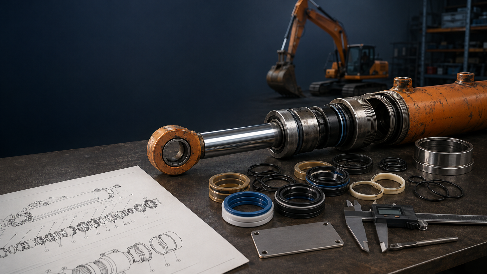
During disassembly, photograph each layer before removing it. Place components in order on a clean surface and assign a number to every seal and ring. The orientation of a U-cup, buffer seal or wiper is as important as its dimensions.
Step 2: Measure the hydraulic cylinder rod
Measure the outside diameter of the polished chrome rod with a micrometer or suitable caliper. Take readings at several points around the circumference and along an unworn area of the rod.
Do not measure over rust, scoring, raised metal, paint or plating buildup. If readings vary, record the range rather than rounding immediately. A worn rod can produce a smaller reading than its original nominal size.
Step 3: Measure the cylinder bore
The bore is the internal diameter of the cylinder barrel. Use an inside micrometer or bore gauge when possible. Measure in more than one direction and at several depths to detect ovality, taper or wear.
Do not assume that the piston’s measured outside diameter equals the nominal bore. The piston requires operating clearance, and wear rings or guide rings may control its relationship with the barrel.
Step 4: Measure the gland and piston grooves
New seals must fit the hardware grooves, so groove dimensions are often more dependable than distorted old seals. For each groove, record:
- Groove diameter
- Groove width
- Groove depth
- Corner radius or chamfer where relevant
- Whether the groove is open, split or closed
- The seal’s installed orientation
Rod-seal grooves are measured in the gland or head. Piston-seal grooves are measured on the piston. Wiper, buffer, O-ring, backup-ring and wear-ring grooves should be recorded separately.
Seal manufacturers specify installation dimensions, tolerances, clearances and surface requirements for individual profiles. Parker notes that gland design and installation conditions vary, while Trelleborg’s hydraulic seal guidance identifies separate rod or bore, groove diameter, width, radius and clearance dimensions. Do not apply one generic groove formula to every seal profile.
Step 5: Measure each removed seal
For each component, record the following dimensions in the same unit:
| Dimension | Meaning | Measurement tip |
|---|---|---|
| Inside diameter (ID) | The smallest functional diameter through the seal | Keep the seal circular and avoid stretching soft material. |
| Outside diameter (OD) | The largest functional outside diameter | Exclude flexible lips unless the profile specification uses them. |
| Height or width | The axial thickness of the seal | Apply minimal measuring pressure to avoid compression. |
| Cross-section | Profile size of an O-ring or ring | Measure in several places away from the compression set. |
| Profile | Shape, lips, energizer and pressure direction | Draw or photograph the cross-section; dimensions alone may not identify it. |
For a rigid wear ring, also measure ring thickness, width and installed gap if available. Wear rings guide the piston or rod and help prevent metal-to-metal contact; they are not interchangeable with pressure seals.
Step 6: Identify the seal type and pressure direction
A measurement such as 50 × 65 × 10 mm does not fully describe a seal. Record whether it is a rod seal, piston seal, wiper, buffer seal, static O-ring, backup ring or guide ring.
- Rod seal: retains hydraulic fluid around the moving rod.
- Wiper: removes dirt and moisture as the rod retracts.
- Buffer seal: protects the primary rod seal from pressure spikes.
- Piston seal: separates pressure across the piston.
- Wear or guide ring: carries side load and prevents metal contact.
- O-ring and backup ring: provide static sealing or energize another sealing element.
Mark which side faced the pressure. A reversed profile can leak even when every dimension is correct.
Step 7: Determine whether the cylinder uses metric or inch dimensions
Record the original measurement before converting. One inch equals exactly 25.4 mm, but a value close to an inch fraction does not prove that the cylinder is inch-sized. Compare several independent dimensions and check the machine’s origin, cylinder number and catalog data.
| Inches | Millimetres |
|---|---|
| 1/2 in | 12.7 mm |
| 3/4 in | 19.05 mm |
| 1 in | 25.4 mm |
| 1 1/2 in | 38.1 mm |
| 2 in | 50.8 mm |
| 3 in | 76.2 mm |
| 4 in | 101.6 mm |
Do not round 50.8 mm to a nominal 50 mm without additional evidence. That small difference can determine whether a seal fits correctly.
How wear and damage affect measurements
Used seals rarely retain their original geometry. Consider these effects:
- Elastomers may swell after exposure to incompatible fluid.
- Heat and age can cause shrinkage or hardening.
- Compression set can flatten an O-ring or sealing lip.
- Extrusion can increase one part of the outside dimension.
- Wear can reduce lip thickness or remove identifying features.
- PTFE elements can take a permanent installed shape.
When a used seal and its groove give conflicting results, report both measurements and provide photographs. Do not “correct” the values without telling the supplier.
Hydraulic cylinder seal measurement worksheet
For each inquiry, prepare a record containing:
- Machine brand, model and serial number
- Cylinder position and cylinder assembly number
- Rod diameter and cylinder bore
- Numbered list of every seal and ring
- ID × OD × height for each seal
- Groove diameter, width and depth
- Seal profile drawing and pressure direction
- Metric or inch units
- Hydraulic fluid, operating temperature and known pressure
- Clear photographs with a ruler or scale
Keep measurements in a table instead of sending unlabeled photos. This allows the supplier to compare the complete sealing system rather than guessing from a single component.
Common measurement mistakes
- Ordering by excavator model without specifying the cylinder
- Measuring only the rod and bore
- Mixing millimetres and inches in one record
- Rounding measurements too early
- Measuring flexible seal lips as the body diameter
- Using only worn seal dimensions and ignoring the groove
- Mixing the installation order during cleaning
- Selecting by colour instead of profile and material
- Ignoring a replaced or aftermarket cylinder
Frequently asked questions
Can I identify a seal kit from rod and bore diameter alone?
No. Rod and bore measurements narrow the possibilities, but groove sizes, seal profiles, cylinder position and hardware design are also required.
Should I measure the old seal or the groove?
Measure both. The groove often preserves the intended hardware dimensions, while the old seal shows the profile and arrangement. Used seals may be worn, swollen or permanently deformed.
How accurate should the measurements be?
Use calibrated tools and record the displayed value without premature rounding. Required tolerances depend on the seal profile and size, so the final selection should be checked against manufacturer data.
How do I measure a soft O-ring accurately?
Measure its inside diameter and cross-section without stretching or compressing it. Take several cross-section readings away from the flattened contact area and compare them with the groove.
Can I choose a hydraulic seal by colour?
No. Colour is not a dependable identification method. Different manufacturers can use different pigments, and service exposure can change appearance.
What information should I send for help?
Send the cylinder number, machine details, cylinder position, rod and bore measurements, groove dimensions, numbered seal measurements and clear photographs. Browse our Caterpillar, Komatsu and Hitachi excavator seal kits, or contact Fujis Seal at cmx@fujis-seal.com.
Technical references
- Parker Performance Sealing Products for Hydraulic Fluid Power Equipment
- Trelleborg Hydraulic Seals technical catalog
Summary
The correct process is to identify first and measure second. Preserve the seal arrangement, measure the rod, bore, hardware grooves and every seal profile, and document wear or uncertainty. Combine those measurements with the cylinder number, machine serial number and operating conditions before selecting a replacement kit.
Manufacturer names and technical references are used for identification and educational purposes. Unless a product listing states otherwise, products sold by Fujis Seal are aftermarket replacement parts and are not represented as being manufactured or endorsed by the original equipment manufacturer.